Spheres in High Dimensions, Part 4
This continues the discussion of hyperspheres. If you have somehow navigated here without first going through the earlier sections, please go to Part 1 for a statement of the problem and links to Part 2 and Part 3. Otherwise, what follows will probably be meaningless.
Hyperspheres and hyperspace may seem like mathematical inventions, with no practical applications. But that is far from the truth.
Optical character recognition (OCR) is an important tool for converting hard copy (paper) documents into a form that can be stored on a computer. OCR utilizes a large number of measurements in its attempt to classify the characters of the text. Each measurement is represented as one coordinate in a large vector. If there are 20 measurements, then the vector has 20 components and lives in 20-dimensional space, and understanding the geometry of hyperspace becomes important to devising good OCR programs.
Efficient modulation techniques, such as those used in a DSL or cable modem, also use high dimensional representations to get higher data rates. In many cases, data is encoded onto short pulsed signals at different frequencies. Mathematically it turns out that each pulse at each frequency can be viewed as an additional dimension in a high dimensional signal space.
For example, suppose that the modem can transmit a thousand pulses a second with each pulse therefore being 1 msec long. Suppose also that it can transmit these pulses at frequencies of 1 kHz (1,000 cycles per second), 2 kHz and 3 kHz. Since a 1 kHz signal has 1,000 cycles per second, a 1 msec pulse will have exactly 1 cycle of that sine wave. Similarly, these 1 msec pulses will contain 2 cycles of the 2 kHz frequency, and 3 cycles of the 3 kHz frequency.
We'll also assume that the modem can transmit pulses at all three frequencies simultaneously without interference among the pulses at the receiver. This makes sense since a receiver can tune to each "channel" (each frequency), much as your FM radio or TV tuner can tune to different stations, with all the stations coexisting without interference among them. By having three such receivers rolled into one "super receiver," the super receiver can listen to all three channels (1 kHz, 2 kHz and 3 kHz) at the same time and extract information from each channel.
(What I have called a super receiver is usually called a modem. Modem is a contraction of "modulator-demodulator." Modulation is the process of transforming data into a form that can be transmitted over the channel available to us, and demodulation is the process of extracting that information from the channel. Modems can transmit and receive data since we want communications in both directions over the channel. For example, you need to send requests to your ISP and your ISP then needs to send the web pages corresponding to those requests to you.)
If each pulse can assume two amplitudes, say 0 volts or 1 volt, then each pulse can convey 1 bit of data. The overall data rate will then be 3,000 bits per second since we have three subchannels, each conveying 1,000 bits of data (on-off pulses) per second.
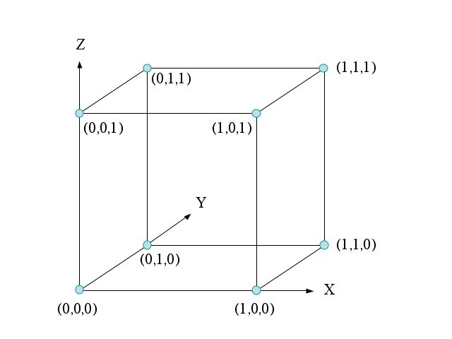
If we just send each bit on a single pulse then, even though there are 3,000 dimensions (pulse-frequency combinations) per second, the high dimensional nature of the space need not be considered since there is no interaction among the different dimensions. Since I cannot draw a 3,000 dimensional picture, let's consider just three dimensions, corresponding to the three pulses that can be sent in the first millisecond, one each at 1 kHz, 2kHz, and 3 kHz. Since each of the three pulses can have amplitude zero or one, there are 2x2x2 = 8 possible signal combinations. We can represent these eight possible signal combinations (called a signal constellation) in three dimensions as shown below.
Figure 1: Signal Constellation of Three Uncoded Bits
The signal at (0,0,0) corresponds to all three bits being 0's and causes the transmitted signal to be zero for the 1 millisecond we are considering.
The signal at (0,0,1) corresponds to the 1 kHz and 2 kHz pulses having zero amplitude, but the 3 kHz pulse having amplitude 1 and thus the transmitted signal is
s(t) = sin(2 π 3000 t)
for 0<t<1 msec. It conveys the bit pattern 001. [Note: You may be used to thinking of angles as measured in degrees, while the above equation uses angles measured in radians. For a brief explanation of radians, and why they are the better unit to use in this discussion, click here.]
The signal at (1,1,1) corresponds to all three pluses having amplitude 1 so that the transmitted signal is
s(t) = sin(2 π 1000 t) +sin(2 π 2000 t) + sin(2 π 3000 t)
for 0<t<1 msec. It conveys the bit pattern 111.
While I have represented these signals in a three dimensional space, their independence would have allowed me to use a simpler one dimensional space (a line) for each signal, as shown below.
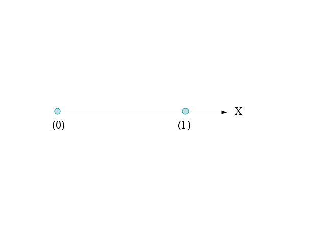
Figure 2: Signal Constellation of One Uncoded Bit
The three dimensional Figure 1 can be obtained by repeating the one dimensional Figure 2 in each of three dimensions.
But, if there is noise on the channel, and there always is, then we will sometimes make errors in demodulating the bits. Whenever the noise is large enough to make a 1 volt pulse look more like a 0 volt pulse, or vice versa, an error will occur. To help minimize the effects of noise, efficient modems use more complex modulation. For example, the three dimensional signal constellation shown in Figure 3 below allows only four of the eight possible combinations that were shown in Figure 1.
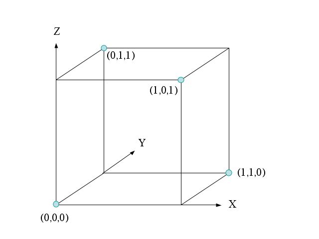
Figure 3: Signal Constellation of Two Coded Bits in Three Dimensions
Since only four signals are allowed, we can now only convey two bits of information, not three as in Figure 1. For example, we can take the first two transmitted amplitudes (in the X and Y directions, corresponding to the amplitudes of the 1 and 2 kHz pulses) as our information bits, with the third bit (in the Z direction, corresponding to the 3 kHz pulse's amplitude) being non-informational or redundant. In fact, the third bit in each of the four allowed signals
{(0,0,0), (0,1,1), (1,0,1), (1,1,0)}
is the exclusive-or, abbreviated XOR, of the first two bits, so it is clearly redundant. The XOR of two bits is 1 if one, but not both of the bits are 1. Otherwise the XOR is 0. This is almost the same as the normal OR logical operation, in which the output is 1 if at least one of the inputs is 1. The "exclusive" part of XOR relates to the fact that we exclude the possibility of both bits being 1 causing the output to be 1.
The signal constellation of Figure 3 cannot be reduced to three one-dimensional signals that are combined together, as was the case in Figure 1. Now there is an interdependence among the bits that demands a three dimensional representation.
Figure 3's constellation has an advantage over that of Figure 1 in that it has greater immunity to noise. In most channels, the probability of a noise vector drops off rapidly as the length of the noise vector increases. Looking at Figure 1, or its reduction to one dimension in Figure 2, we see that noise vectors slightly larger than 0.5 in length can cause errors. For example, in Figure 1, if I transmit the signal (0,0,0) and a noise vector of (0.6, 0, 0) is added to it, the received signal will be (0.6, 0, 0) and look more like (1,0,0) than the transmitted signal.
But, the signal constellation of Figure 3 is immune to all noise vectors smaller than 0.707 in length. That is because the closest distance between any two signal vectors is now 1.414. [Hint: Look at the figure and use the Pythagorean Theorem to find distances between pairs of the four possible signals.]
The larger noise vector required to cause an error translates into a greatly reduced error probability. Of course, this is achieved at the cost of a reduction in transmitted rate. In Figure 1, we were transmitting 3,000 bits per second, whereas in Figure 3, we are only transmitting 2,000 bits of information per second. (We are transmitting 3,000 bits of data per second, but only 2/3 of those bits convey information. The third bit of each triple is redundant and conveys no information.) Even when this cost is taken into account, there are channels for which the coded signal constellation of Figure 3 conveys more information than the uncoded constellation of Figure 1. Large amounts of noisy data can convey less information than small amounts of more reliable data. (There are ways to measure the information in noisy data, using information theory, but that's beyond what we're covering here.)
The signal constellation of Figure 3, while improved over that of Figure 1, is still far from optimal and today's high performance DSL or cable modems use much more complex signals that depend even more on properties of hyperspace.
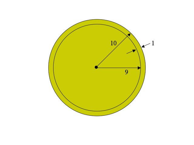
In fact, the motivation for my asking this question on the Ph.D. qualifying exam comes from a property called "sphere hardening" that plays an important role in the design of high performance modulation systems. Sphere hardening refers to the fact that, in high dimensional space, the volume of a sphere lies almost entirely near its surface. We saw that vividly when, in 100 dimensions, only $26 out of the full $1,000,000 of gold was in the inner sphere of radius 9. Almost all the gold was in the thin shell of thickness 1 that lay near the surface of the larger sphere of radius 10.
Contrast that with the picture in two dimensions shown below, where most of the volume (area) of this two dimensional sphere (a circle) lies in the inner sphere.
This completes our discussion of hyperspheres. I hope you have enjoyed it. Should you need them, here are links to:
Part 1 of this discussion of hyperspheres
Part 2 of this discussion of hyperspheres
Part 3 of this discussion of hyperspheres
This page can be viewed in Romanian courtesy of azoft.